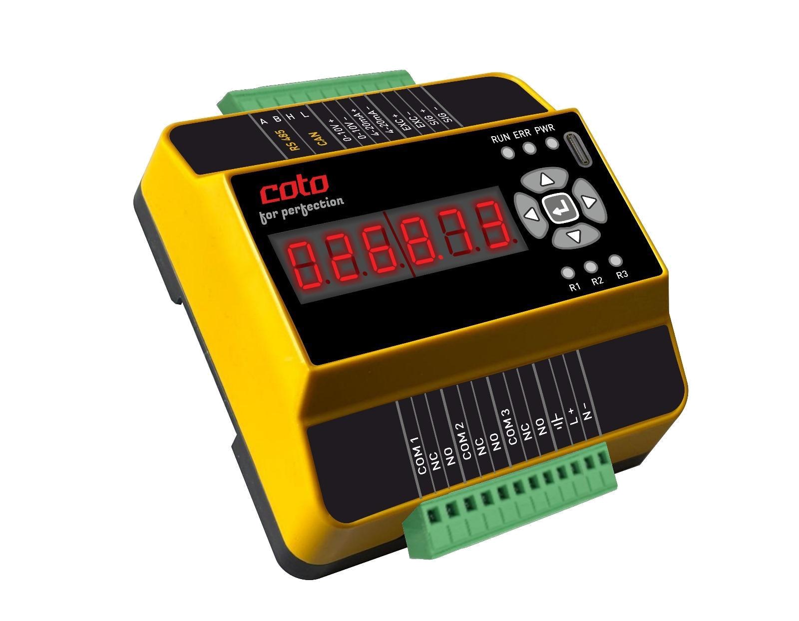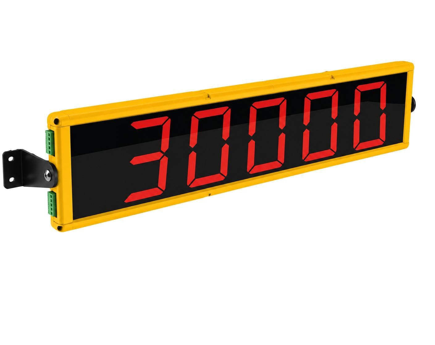
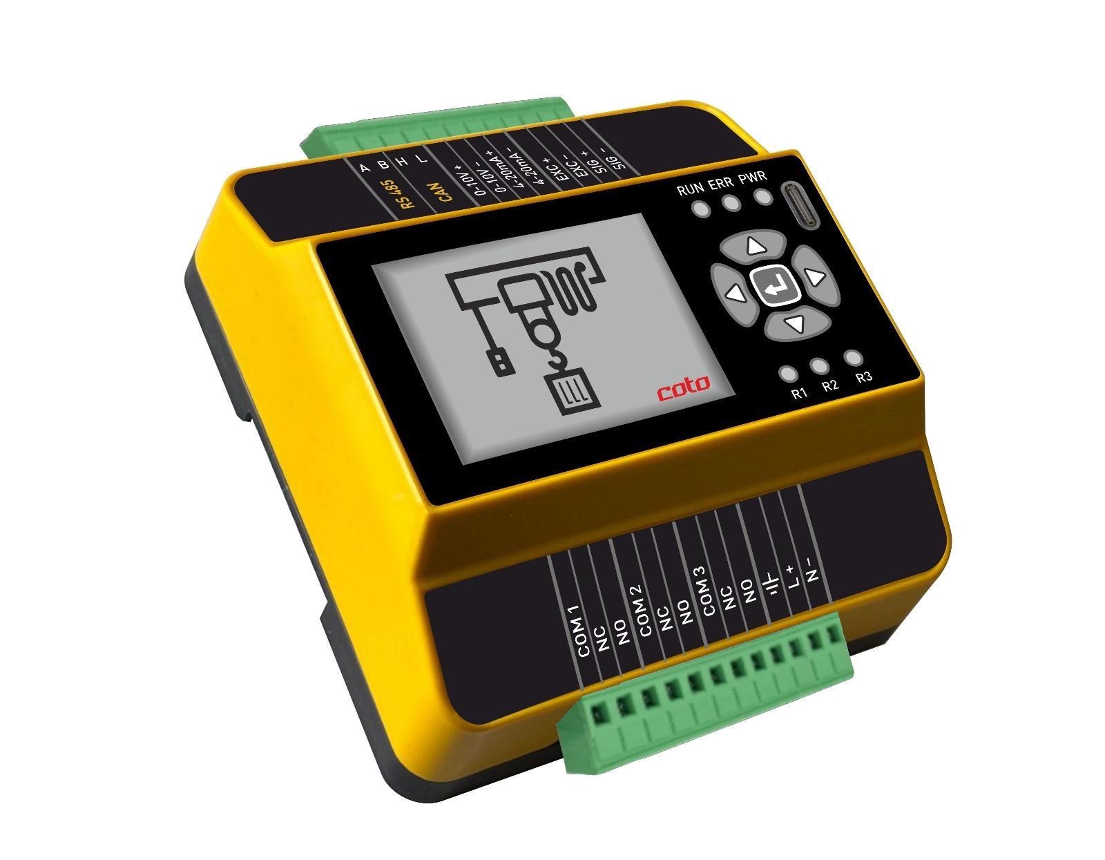
Overview
Beyond overload protection, CLB evaluates load, rope angle (CAS), wind and drive data together: load-dependent speed stages, slack-rope protection, VFD monitoring, Anti-Sway data transfer and Anti-Grab controlled lifting. Overloads, lifting cycles and inverter data are logged for full operational traceability (BLACKBOX).
Key Features
Smart Safety & Motion Control
- Overload protection with alarm and pre-alarm thresholds
- Load-dependent speed: 3rd and 4th speed stages via relays below nominal load
- Rope angle control with CAS (X/Y) against side pull
- Wind monitoring via CWS anemometer input
- Slack-rope protection: lowering is stopped at a defined negative load threshold
- VFD monitoring of status, phase, current and fault codes via Modbus
- Anti-Sway: rope angle and position data to PLC/drive via Modbus
- Anti-Grab: linear frequency ramp for smooth load pick-up
Inputs / Outputs & Communication
- 2 independent load cell inputs (350 Ω, 10 VDC)
- 4 relay outputs: three changeover + one safety changeover relay with guided contacts
- 2 digital inputs, 2+2 selectable analog inputs / outputs
- RS485/RS232 serial ports; Modbus integration
- Integrated RF interface for connecting multiple units (option)
- 2" full-colour TFT display; LED relay status indicators; 5-key keypad
SCM® App Functions
- Calibration and tare via iOS / Android app
- Individual configuration of the four relay outputs
- Gyroscope or anemometer input
- Communication with frequency inverters via Modbus
- Recording of overvoltage, overcurrent, over-temperature and inverter fault codes
- Real-time recording of overload events and lifting cycles
- Real-time recording of weighing results with product-type information
- Export of records in Excel or PDF format and report printing
Main Functions
- Connection to PC/PLC via RS485/RS232
- Connection to a remote display via RS485/RS232
- Up to 2 load cells in parallel via junction box
- Connection to other units for the summing function via RS485 or RF (option on request)
- Continuous load cell connection integrity check
- Digital filter to reduce the effects of load oscillation
- Theoretical calibration (via keypad) and real calibration (with sample weights)
- Tare weight zero setting
- Automatic zero setting at power-on
- Gross weight zero tracking
Ordering Code
Example
CLB-1-1-2-1-M-1-J| CLBProduct family | 1Function | 1Data transfer | 2Relays | 1Load cell inputs | MCommunication | 1Wireless | JOptional input |
|---|---|---|---|---|---|---|---|
|
|
|
|
|
|
|
|
Technical Specifications
| Power supply and consumption | 24–250 VDC/VAC; 6 VA |
|---|---|
| Number of load cells • Load cell supply | up to 2 (350 Ω) • 10 VDC |
| Linearity | < 0.01% full scale |
| Thermal drift | < 0.002% full scale / °C |
| A/D converter | 24 bit |
| Measuring range | ±3.9 mV |
| Conversions per second | 3 |
| Decimals • Display increments | 0÷4 • x1 x2 x5 x10 x20 x50 |
| Digital filter | 0.25÷3 Hz |
| Relay outputs | 4 changeover relay outputs – 30 VDC / 250 VAC; 2 A |
| Opto-isolated digital inputs | 2 |
| Serial ports | RS485, RS232 |
| Baud rate | 1200, 2400, 9600, 19200, 38400, 57600, 115200 bit/s |
| Humidity (non-condensing) | 85% |
| Storage temperature | −30 °C … +60 °C |
| Operating temperature | −20 °C … +55 °C |
Certifications & Compliance
- CE certification for European Union countries.
- Category 2 as per EN 13849-1, PL d (comparable to SIL 2 level, EN 62061) (LCD3PL).
- Lead (Pb) free.
Options on Request
CED-3X / CED-4X
IP54 aluminium 6-digit external display with RS232/RS485 communication. 3": 6 × 76 mm LED, 620 × 150 × 100 mm; 4": 6 × 102 mm LED, 770 × 150 × 100 mm.
CLP / CLW
IP66 pin type and wire rope type load cells, standard 4G0.22 mm² 3.5 m cable.
RF
Integrated RF interface for connecting multiple units: 2.4 GHz (128 channels), average range 100 m.
The company reserves the right to change technical data, drawings and images without prior notice.